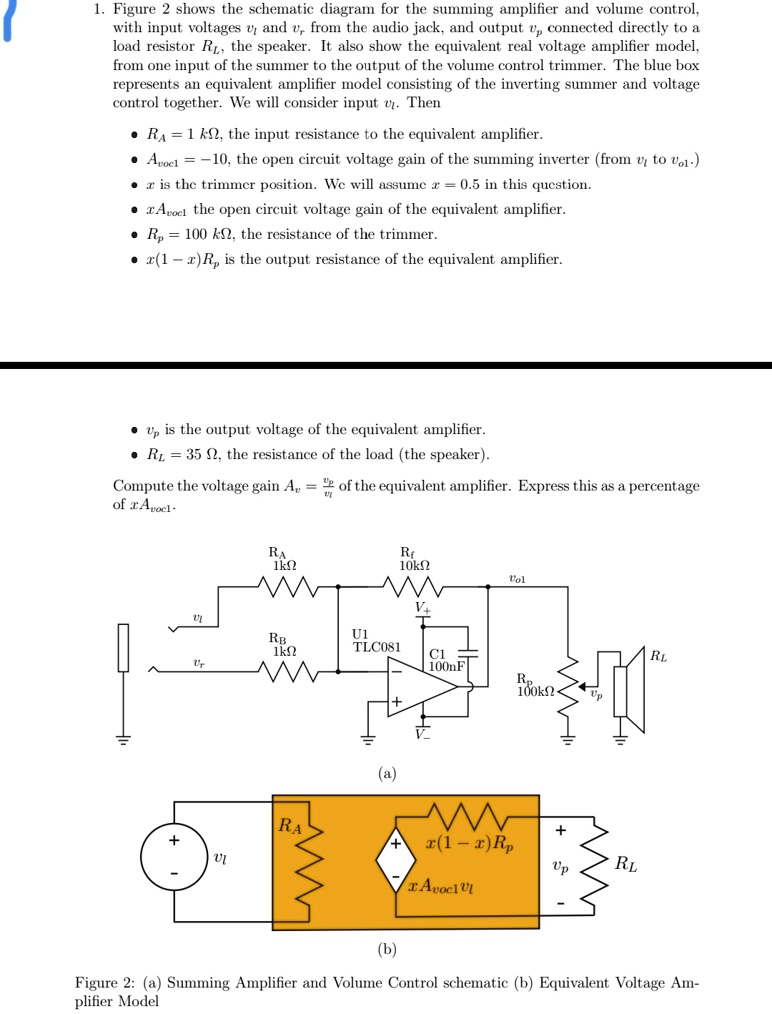
1. Figure 2 shows the schematic diagram for the summing amplifier and volume control, with input voltages $v_i$ and $v_r$, from the audio jack, and output $v_{ol}$ connected directly to a load resistor $R_L$, the speaker. It also show the equivalent real voltage amplifier model, from one input of the summer to the output of the volume control trimmer. The blue box represents an equivalent amplifier model consisting of the inverting summer and voltage control together. We will consider input $v_r$. Then
• $R_A = 1 k\Omega$, the input resistance to the equivalent amplifier.
• $A_{voc1} = -10$, the open circuit voltage gain of the summing inverter (from $v_i$ to $v_{ol}$).
• $x$ is the trimmer position. We will assume $x = 0.5$ in this question.
• $A_{vocL}$ the open circuit voltage gain of the equivalent amplifier.
• $R_p = 100 k\Omega$, the resistance of the trimmer.
• $x(1-x)R_p$ is the output resistance of the equivalent amplifier.
• $v_p$ is the output voltage of the equivalent amplifier.
• $R_L = 35 \Omega$, the resistance of the load (the speaker).
Compute the voltage gain $A_v = \frac{v_p}{v_r}$ of the equivalent amplifier. Express this as a percentage of $A_{vocL}$.