4. (10pts)
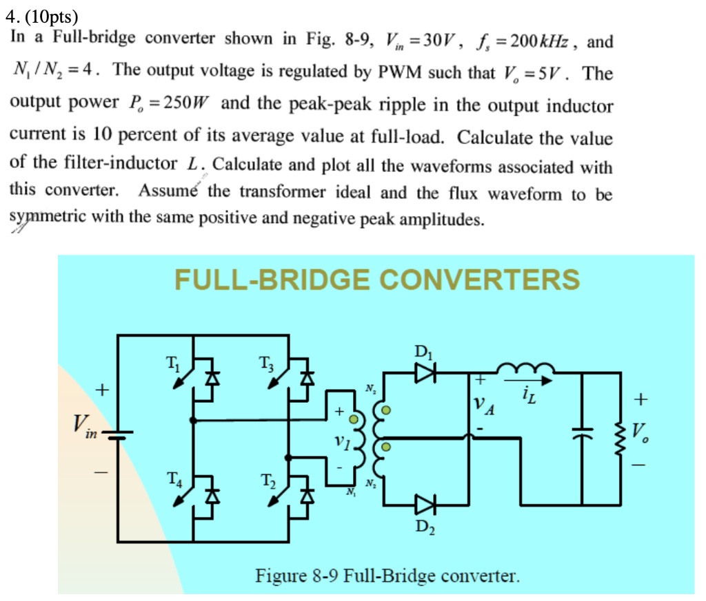
In a Full-bridge converter shown in Fig. 8-9, $V_{in} = 30V$, $f = 200kHz$, and
$N_1/N_2 = 4$. The output voltage is regulated by PWM such that $V_o = 5V$. The
output power $P_o = 250W$ and the peak-peak ripple in the output inductor
current is 10 percent of its average value at full-load. Calculate the value
of the filter-inductor $L$. Calculate and plot all the waveforms associated with
this converter. Assume the transformer ideal and the flux waveform to be
symmetric with the same positive and negative peak amplitudes.
FULL-BRIDGE CONVERTERS
$V_{in}$
+
$T_1$
$T_3$
$N_2$
+
$V_1$
$T_4$
$T_2$
$N_1$
$N_1$
$D_1$
$i_L$
+
$V_A$
$V_o$
$D_2$
Figure 8-9 Full-Bridge converter.