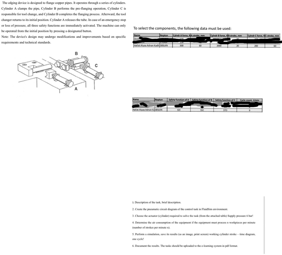
The edging device is designed to flange copper pipes. It operates through a series of cylinders.
Cylinder A clamps the pipe, Cylinder B performs the pre-flanging operation, Cylinder C is
responsible for tool change, and Cylinder B completes the flanging process. Afterward, the tool
changer returns to its initial position. Cylinder A releases the tube. In case of an emergency stop
or loss of pressure, all three safety functions are immediately activated. The machine can only
be operated from the initial position by pressing a designated button.
Note: The device's design may undergo modifications and improvements based on specific
requirements and technical standards.
To select the components, the following data must be used:
Neptun Cylndr A force, NA stroke, mm Cylndr B force, NB stroke, mm Cylndr C force, NC stroke, mm
Deeb
Hallat Alyaa Adnan Kadh SBSLKN 300 60 2000 20 200 60
B
A
C
Neptun Safety function of A Safety function of B Safety function of C Cycle count, 1/min
Hallat Alyaa Adnan KaSBSLKN SDI SSC STO 9
1. Description of the task, brief description.
2. Create the pneumatic circuit diagram of the control task in FluidSim environment.
3. Choose the actuator (cylinder) required to solve the task (from the attached table) Supply pressure 6 bar!
4. Determine the air consumption of the equipment if the equipment must process n workpieces per minute
(number of strokes per minute n).
5. Perform a simulation, save its results (as an image, print screen) working cylinder stroke - time diagram,
one cycle!
6. Document the results. The tasks should be uploaded to the e-learning system in pdf format.