0.0/15.0 points (graded)
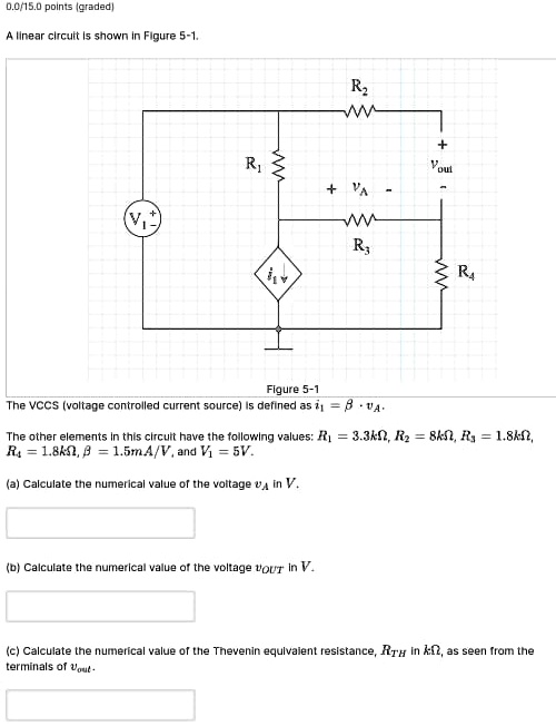
A linear circuit is shown in Figure 5-1.
R2
W
R1
+ Vout
+ VA -
R3
R4
Figure 5-1
The VCCS (voltage controlled current source) is defined as $i_1 = \beta \cdot v_A$.
The other elements in this circuit have the following values: $R_1 = 3.3k\Omega$, $R_2 = 8k\Omega$, $R_3 = 1.8k\Omega$,
$R_4 = 1.8k\Omega$, $\beta = 1.5mA/V$, and $V_1 = 5V$.
(a) Calculate the numerical value of the voltage $v_A$ in V.
(b) Calculate the numerical value of the voltage $v_{OUT}$ in V.
(c) Calculate the numerical value of the Thevenin equivalent resistance, $R_{TH}$ in $k\Omega$, as seen from the
terminals of $v_{out}$.