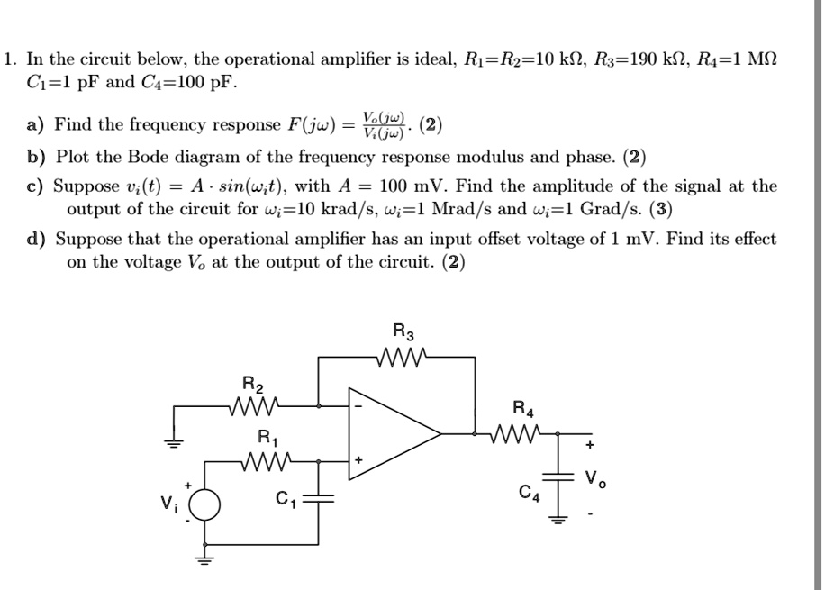
1. In the circuit below, the operational amplifier is ideal, $R_1 = R_2 = 10 \text{ k}\Omega$, $R_3 = 190 \text{ k}\Omega$, $R_4 = 1 \text{ M}\Omega$
$C_1 = 1 \text{ pF}$ and $C_4 = 100 \text{ pF}$.
a) Find the frequency response $F(j\omega) = \frac{V_o(j\omega)}{V_i(j\omega)}$. (2)
b) Plot the Bode diagram of the frequency response modulus and phase. (2)
c) Suppose $v_i(t) = A \cdot \sin(\omega_i t)$, with $A = 100 \text{ mV}$. Find the amplitude of the signal at the
output of the circuit for $\omega_i = 10 \text{ krad/s}$, $\omega_i = 1 \text{ Mrad/s}$ and $\omega_i = 1 \text{ Grad/s}$. (3)
d) Suppose that the operational amplifier has an input offset voltage of 1 mV. Find its effect
on the voltage $V_o$ at the output of the circuit. (2)