Part 3: Building the circuit on the breadboard and taking measurements
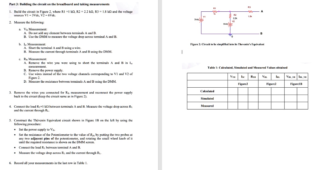
1. Build the circuit in Figure 2, where R1 =1 ??, R2 = 2.2 ??, R3 = 1.8 k? and the voltage
sources V1=3Vdc, V2 = 6Vdc.
2. Measure the following:
a. $V_{th}$ Measurement:
A. Do not add any element between terminals A and B.
B. Use the DMM to measure the voltage drop across terminal A and B.
b. $I_{sc}$ Measurement:
A. Short the terminal A and B using a wire.
B. Measure the current through terminals A and B using the DMM.
c. $R_{th}$ Measurement:
A. Remove the wire you were using to short the terminals A and B in $I_{sc}$
measurement.
B. Remove the power supply.
C. Use wires instead of the two voltage channels corresponding to V1 and V2 of
Figure 2.
D. Measure the resistance between terminals A and B using the DMM.
3. Remove the wires you connected for $R_{th}$ measurement and reconnect the power supply
back to the circuit (keep the circuit same as in Figure 2).
4. Connect the load $R_L$=1 k? between terminals A and B. Measure the voltage drop across $R_L$
and the current through $R_L$.
5. Construct the Thévenin Equivalent circuit shown in Figure 1B on the left by using the
following procedure:
• Set the power supply to $V_{th}$
• Set the resistance of the Potentiometer to the value of $R_{th}$ by putting the two probes at
any two adjacent pins of the potentiometer, and rotating the small wheel knob of it
until the required resistance is shown on the DMM screen.
• Connect the load $R_L$ between terminal A and B.
• Measure the voltage drop across $R_L$, and the current through $R_L$.
6. Record all your measurements in the last row in Table 1.