The following assembly language program is being run on the 5-stage AVR pipeline that we studied in the lecture notes:
sub r26, r2
ld r5, Y
st X, r7
add r7, r5
The program is run on four different AVR micro-architectures with the following capabilities:
1. Single-cycle execution (no pipeline capability).
2. Pipeline capability with stalling only.
3. Pipeline capability with forwarding only.
4. Pipeline capability with stalling used to enable forwarding.
a) For each of the micro-architectures described above, draw a pipeline timeline diagram for each of the assembly language instructions. If applicable, use arrows to indicate when forwarding occurs between stages on your pipeline diagrams. You do not have to label your arrows.
b) Determine the average latency (in clock cycles) and throughput (in instructions/cycle) for each of the micro-architectures described above. For a fair comparison, express your answers in terms of clock cycles for the pipelined architectures. This means that the single-cycle architecture will require 5 clock cycles to complete a full instruction.
Notes:
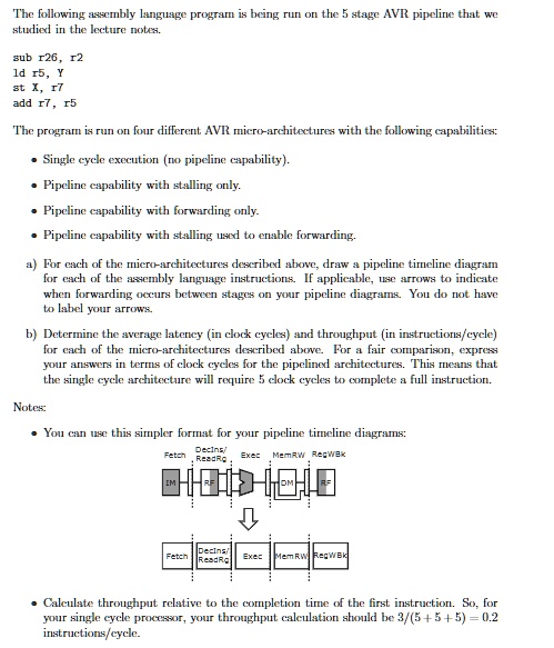
You can use this simpler format for your pipeline timeline diagrams: Decins/ Fetch Exec MemRW RegWBk
Calculate throughput relative to the completion time of the first instruction. So, for your single-cycle processor, your throughput calculation should be 3/(5 + 5 + 5) = 0.2 instructions/cycle.