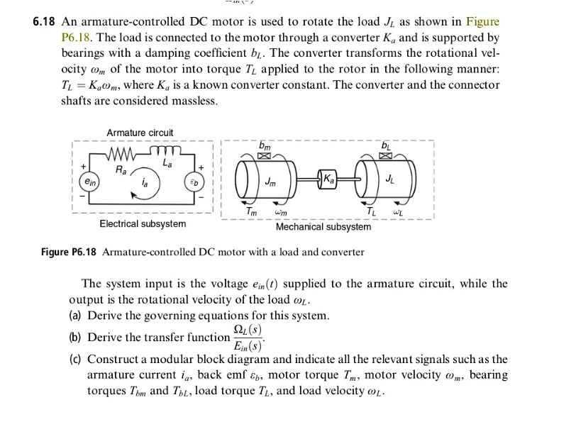
6.18 An armature-controlled DC motor is used to rotate the load $J_L$ as shown in Figure
P6.18. The load is connected to the motor through a converter $K_a$ and is supported by
bearings with a damping coefficient $b_r$. The converter transforms the rotational vel-
ocity $\omega_m$ of the motor into torque $T_L$ applied to the rotor in the following manner:
$T_L = K_a\omega_m$, where $K_a$ is a known converter constant. The converter and the connector
shafts are considered massless.
Armature circuit
$b_m$
$b_L$
$L_a$
$+$$
$R_a$
$+$$
$e_{in}$
$i_a$
$e_b$
Electrical subsystem
Mechanical subsystem
Figure P6.18 Armature-controlled DC motor with a load and converter
The system input is the voltage $e_{in}(t)$ supplied to the armature circuit, while the
output is the rotational velocity of the load $\omega_L$.
(a) Derive the governing equations for this system.
$\frac{\Omega_L(s)}{E_{in}(s)}$
(b) Derive the transfer function
(c) Construct a modular block diagram and indicate all the relevant signals such as the
armature current $i_a$, back emf $e_b$, motor torque $T_m$, motor velocity $\omega_m$, bearing
torques $T_{bm}$ and $T_{bL}$, load torque $T_L$, and load velocity $\omega_L$.