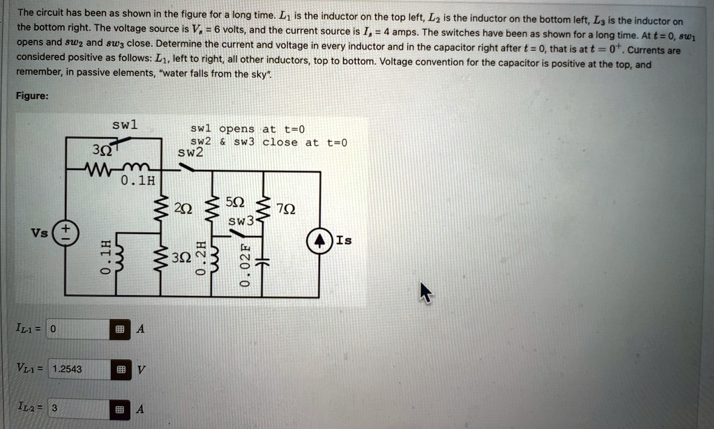
The circuit has been as shown in the figure for a long time. $L_1$ is the inductor on the top left, $L_2$ is the inductor on the bottom left, $L_3$ is the inductor on
the bottom right. The voltage source is $V_s = 6$ volts, and the current source is $I_s = 4$ amps. The switches have been as shown for a long time. At $t = 0$, $sw_1$
opens and $sw_2$ and $sw_3$ close. Determine the current and voltage in every inductor and in the capacitor right after $t = 0$, that is at $t = 0^+$. Currents are
considered positive as follows: $L_1$, left to right, all other inductors, top to bottom. Voltage convention for the capacitor is positive at the top, and
remember, in passive elements, \"water falls from the sky\".