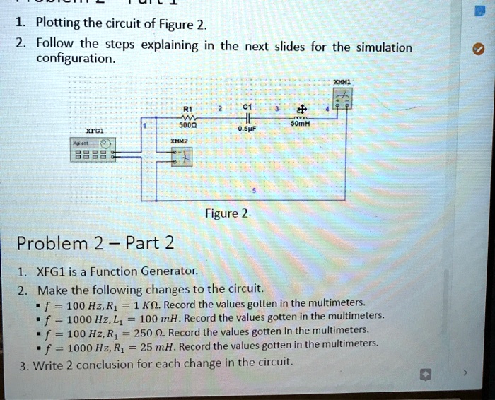
1. Plotting the circuit of Figure 2.
2. Follow the steps explaining in the next slides for the simulation
configuration.
R1 2 C1 3
ww
5000
50mH
XFG1
0.5µF
XMM2
Agilent
Figure 2.
XMM1
Problem 2 - Part 2
1. XFG1 is a Function Generator.
2. Make the following changes to the circuit.
\(f = 100\text{ Hz}, R_1 = 1\text{ k}\Omega\). Record the values gotten in the multimeters.
\(f = 1000\text{ Hz}, L_1 = 100\text{ mH}\). Record the values gotten in the multimeters.
\(f = 100\text{ Hz}, R_1 = 250\text{ }\Omega\). Record the values gotten in the multimeters.
\(f = 1000\text{ Hz}, R_1 = 25\text{ mH}\). Record the values gotten in the multimeters.
3. Write 2 conclusion for each change in the circuit.