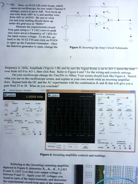
Next, on NI ELVIS click Scope, which opens an oscilloscope. Be sure under Channel 0 settings, the source is set to A10. Now hook up one wire from A10+ to v, and another wire from AI0- to AGND. Be sure to click run, and your reading should show up under the grid next to RMS. Measure the experimental closed-loop gain using a 1 V (AC zero-to-peak v. sine wave set at a frequency of 1 kHz for the input source voltage. To do this, go back to the NI ELVIS and click on FGEN to open up the Function Generator. Once the function generator is open, change the frequency to 1 kHz, Amplitude (Vpp) to 10.00, and be sure the Signal Route is set to AO 1. Move the wire over from AO 0 to AO 1, then click Run. Refer to Figure 6 and 7 for the wiring and control settings. On your oscilloscope, change the Time/Div to 500us. Your screen should look like Figure 6. Sketch what you see on the oscilloscope screen and explain in your own words what an inverting amplifier does. Repeat both the DC and the AC experiments with the combination R and Ry that will give you a gain from 25 to 30. What do you conclude? tor-N BVSm -a VEW 1.0000 kHz LbVIEW - IS Figure 6: Inverting amplifier controls and readings Referring to the inverting summing amplifier depicted in Figure 8, determine Ra, R, VA0 0, and VA0 1 so that your output voltage is between 9 and 12. Apply your DC voltages you found to each of the input terminals and determine...