Texts: R1 = 15kΩ
Q1 = 2N3904
V2 = 15V
Generator V1 = 1Vpk, 1kHz Function
Output
LR2 = 4.7kΩ
V3 = 15V
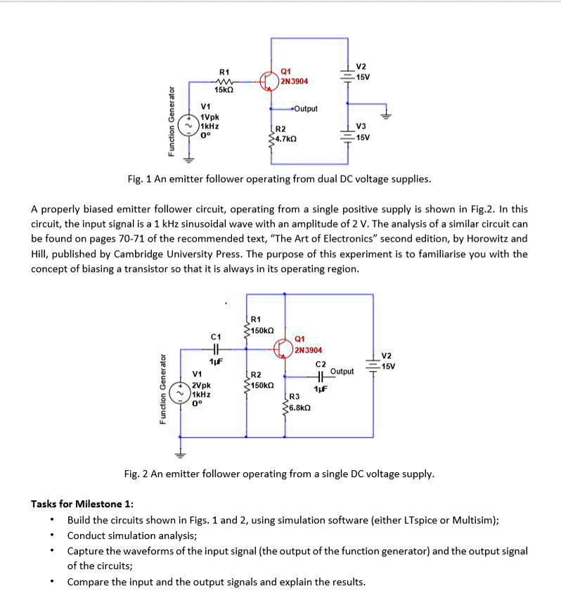
Fig.1: An emitter follower operating from dual DC voltage supplies
A properly biased emitter follower circuit, operating from a single positive supply, is shown in Fig.2. In this circuit, the input signal is a 1kHz sinusoidal wave with an amplitude of 2V. The analysis of a similar circuit can be found on pages 70-71 of the recommended text, "The Art of Electronics, second edition," by Horowitz and Hill, published by Cambridge University Press. The purpose of this experiment is to familiarize you with the concept of biasing a transistor so that it is always in its operating region.
R1 = 150kΩ
C1 = 1μF
V1 = 2Vpk, 1kHz, 0V
Q1 = 2N3904
C2 = 1μF
R2 = Output
H1 = 150kΩ
R3 > 6.8kΩ
Generator Function
V2 = 15V
Fig.2: An emitter follower operating from a single DC voltage supply
Tasks for Milestone 1:
Build the circuits shown in Figs.1 and 2 using simulation software (either LTspice or Multisim). Conduct simulation analysis. Capture the waveforms of the input signal (the output of the function generator) and the output signal of the circuits. Compare the input and the output signals and explain the results.