20 December 2023
We aim to build a single-stage sounding rocket to send a CanSat at the boundary of space, i.e., the Karman line, which is at a conventional altitude of 100km above sea level. You are required to assess a preliminary design of the rocket, including the thrust chamber, the propellant tanks, and the pressurization tank. Neglect the design of piping, valves, and cooling jackets. Draft a sketch of the rocket layout and the thrust chamber indicating the main dimensions (i.e., lengths, diameters, thicknesses, angles). Consider the following requirements and assumptions:
System constraints
Propulsion system chosen to be a liquid rocket engine of the pressure-fed type
Isp=200-250s. (expected range)
Payload mass Mpl=5kg (CanSat)
System mass Msystem=30kg (avionics, recovery system, abort system, wiring, piping, valves, fittings, weldings, etc.)
Structural mass Ms=45kg (note that Msystem is contained in this value, therefore the rest is to be accounted for the mass of tanks and thrust chamber)
TWR=1.8
Burn time tB=85s
ΔVDRAG=600(m)/(s)
1-Thrust chamber
Conical shape for both divergent/convergent portions of the nozzle with αconv=30° and αdiv=15°, however other values can be used: justify your choice in any case.
Mach number at the inlet of the convergent estimated at M2=0.1905
(Hint: ambient pressure varies from 101325Pa at sea level to 0Pa in the vacuum of space. You can use pa=(0.5236)/(B)ar ((1)/(B)ar =10^(5)(Pa)) as an intermediate value for the ambient pressure when assessing the thrust chamber design.)
2-Propellants
The propellants and the associated combustion properties at the given chamber pressure are reported in the following:
PROPELLANTS / P0 (bar) / OF / C* / T0 (k) / density (k(g)/(m)3) / Mw ( k(g)/(k)mol) / γ / U0sound ((m)/(s)) / Pfuel (k(g)/(m)3) / Poxidizer (k(g)/(m)3) / L* (m)
F RP-1 (Tstorage=298k) / 15 / 4.5 / 1645 / 2683 / 1.34 / 19.98 / 1.168 / 1142 / 810 / 1450 / /
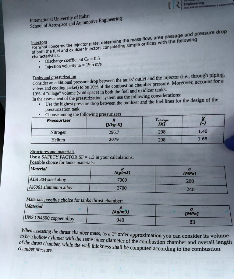
3-Injectors
For what concerns the injector plate, determine the mass flow, area passage, and pressure drop of both the fuel and oxidizer injectors considering simple orifices with the following characteristics:
Discharge coefficient CD=0.5
Injection velocity u1=19.5(m)/(s)
4-Tanks and pressurization
Consider an additional pressure drop between the tanks' outlet and the injector (i.e., through piping, valves, and cooling jacket) to be 10% of the combustion chamber pressure. Moreover, account for a 10% of "ullage" volume (void space) in both the fuel and oxidizer tanks.
In the assessment of the pressurization system use the following considerations:
Use the highest pressure drop between the oxidizer and the fuel lines for the design of the pressurization tank
Choose among the following pressurizers
5-Structures and materials
Use a SAFETY FACTOR SF =1.3 in your calculations.
Possible choice for tanks materials:
Materials possible choice for tanks thrust chamber:
When assessing the thrust chamber mass, as a 1st order approximation you can consider its volume to be a hollow cylinder with the same inner diameter of the combustion chamber and overall length of the thrust chamber, while the wall thickness shall be computed according to the combustion
chamber pressure.
UB
International University of Rabat School of Aerospace and Automotive Engineering For what concerns the injector plate, determine the mass flow, area passage, and pressure drop Injectors characteristics: Discharge coefficient Cp=0.5 Injection velocity u=19.5 m/s Consider an additional pressure drop between the tanks outlet and the injector (i.e., through piping Tanks and pressurization valves and cooling jacket) to be 10% of the combustion chamber pressure. Moreover, account for a 10% of ullage volume (void space) in both the fuel and oxidizer tanks. In the assessment of the pressurization system use the following considerations: Use the highest pressure drop between the oxidizer and the fuel lines for the design of the pressurization tank Choose among the following pressurizers Pressurizer R Tstorage [J/kg-K] [K] Nitrogen 296.7 298 1.40 Helium 2079 298 1.68
Structures and materials Use a SAFETY FACTOR SF=1.3 in your calculations Possible choice for tanks materials: Material p [kg/m3] AISI304 steel alloy 7900 Al6061 aluminum alloy 2700
[MPa]
200
240
Materials possible choice for tanks thrust chamber: Material P [kg/m3] UNS C94500 copper alloy 940
[MPa] 83
chamber pressure.