Digital Parking Control System:
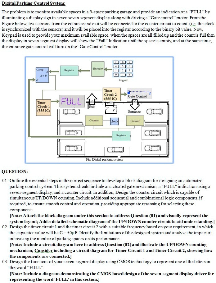
The problem is to monitor available spaces in a 9-space parking garage and provide an indication of a "FULL" by illuminating a display sign in seven seven-segment display along with driving a "Gate control" motor. From the Figure below, two sensors from the entrance and exit will be connected to the counter circuit to count. (i.e. the clock is synchronized with the sensors) and it will be placed into the register according to the binary bit value. Now, Keypad is used to provide your maximum available space, when the spaces are all filled up and the count is full then the display in seven segment display will show the "Full" Indication until the space is empty, and at the same time, the entrance gate control will turn on the "Gate Control" motor.
QUESTION:
01. Outline the essential steps in the correct sequence to develop a block diagram for designing an automated parking control system. This system should include an actuated gate mechanism, a "FULL" indication using a seven-segment display, and a counter circuit. In addition, Design the counter circuit which is capable of simultaneous UP/DOWN counting. Include additional sequential and combinational logic components, if required, to ensure smooth control and operation, providing appropriate reasoning for selecting these components.
[Note: Attach the block diagram under this section to address Question (01) and visually represent the system layout; Add a detailed schematic diagram of the UP/DOWN counter circuit to aid understanding.]
02. Design the timer circuit 1 and the timer circuit 2 with a suitable frequency based on your requirement, in which the capacitor value will be C = 50µF. Identify the limitations of the designed system and analyze the impact of increasing the number of parking spaces on its performance.
[Note: Include a circuit diagram here to address Question (02) and illustrate the UP/DOWN counting mechanism; Consider including a circuit diagram for Timer Circuit 1 and Timer Circuit 2, showing how the components are connected.]
03. Design the functions of your seven-segment display using CMOS technology to represent one of the letters in the word "FULL".
[Note: Include a diagram demonstrating the CMOS-based design of the seven-segment display driver for representing the word 'FULL' in this section.]