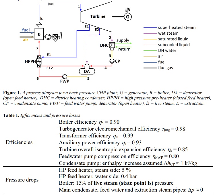
In this assignment, a back pressure cogeneration plant process (see Figure 1) producing district heat (DH) and electricity will be designed based on given supply and return water temperatures and DH production. Personal initial values are listed in Appendix 1, plant and component efficiency assumptions and pressure drops are listed in Table 1. Using the given and chosen values,
• determine pressure, temperature, specific enthalpy, and mass flow rate at each state point
• calculate net electric power, fuel consumption, and efficiencies for electricity and CHP production
• draw the process in a T,s-diagram (boiler pressure drop is assumed to occur entirely in superheaters)
Appendix 1. Personal Initial Values
Fuel: wood chips
ΦDH: 35 MW
TDH,sup: 75°C
TDH,ret: 45°C
pdeaerator: 1.8 bar
Figure 1. A process diagram for a back pressure CHP plant; G = generator, B = boiler, DA = deaerator (open feed heater), DHC = district heating condenser, HPPH = high pressure pre-heater (closed feed heater), CP = condensate pump, FWP = feed water pump, deaerator (open heater), ls = live steam, E = extraction.
Table 1. Efficiencies and Pressure Losses
Boiler efficiency ηb = 0.90
Turbogenerator electromechanical efficiency ηmg = 0.98
Transformer efficiency ηu = 0.99
Auxiliary power efficiency ηs = 0.93
Turbine overall isentropic expansion efficiency ηs = 0.85
Feedwater pump compression efficiency ηFwp = 0.80
Condensate pump: enthalpy increase assumed hcp ~ 1 kJ/kg
HP feed heater, steam side: 5%
HP feed heater, water side: 0.4 bar
Boiler: 15% of live steam (state point Is) pressure
Main condensate, feed water and extraction steam pipes: Δp ~ 0
Efficiencies
Pressure drops