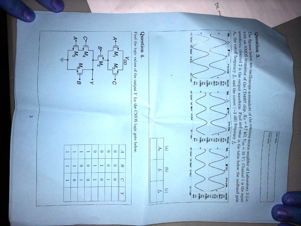
Question 3.
The figures below are oscilloscope screenshots of the common-source amplifier of Laboratory 3 (i.e.
with an NMOS transistor of the CD4007 chip, RD = 4.7 KO, VDD = 10 V). Channel 1 is the input
waveform; channel 2 is the output waveform. Find and enter in the table below the midband gain
Ao, the cutoff frequency ft, and the corner (-3 dB) frequency fp.
Question 4.
Find the logic values of the output Y for the CMOS logic gate below.
VDD
A
B
C
Y
0
0
0
0
0
1
0
0
1
1
0
1
0
1
0
1
1
0
1
1
1
3