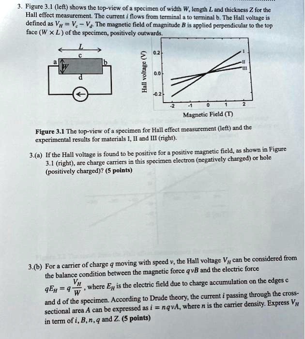
3. Figure 3.1 (left) shows the top-view of a specimen of width W, length L and thickness Z for the Hall effect measurement. The current $i$ flows from terminal a to terminal b. The Hall voltage is defined as $V_H = V_c - V_d$. The magnetic field of magnitude $B$ is applied perpendicular to the top face ($W \times L$) of the specimen, positively outwards.
Figure 3.1 The top-view of a specimen for Hall effect measurement (left) and the experimental results for materials I, II and III (right).
3.(a) If the Hall voltage is found to be positive for a positive magnetic field, as shown in Figure 3.1 (right), are charge carriers in this specimen electron (negatively charged) or hole (positively charged)? (5 points)
3.(b) For a carrier of charge $q$ moving with speed $v$, the Hall voltage $V_H$ can be considered from the balance condition between the magnetic force $qvB$ and the electric force
$qE_H = q\frac{V_H}{W}$, where $E_H$ is the electric field due to charge accumulation on the edges c and d of the specimen. According to Drude theory, the current $i$ passing through the cross-sectional area A can be expressed as $i = nqvA$, where $n$ is the carrier density. Express $V_H$ in term of $i$, $B$, $n$, $q$ and $Z$. (5 points)