For this lab, you will characterize a BJT. You will use Module Y-0016/007. Please follow the
instructions, provide the results, answers to the below questions and simulate experiment in
Multisim Program. You must submit your reports by May 19-20, 2025.
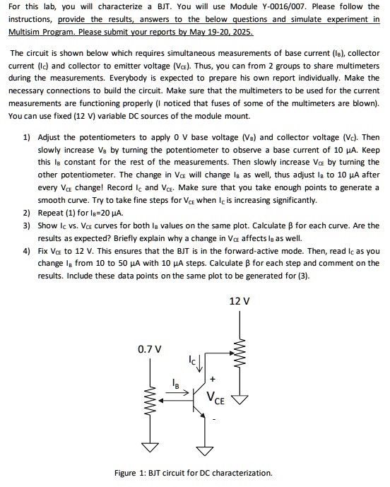
The circuit is shown below which requires simultaneous measurements of base current ($I_B$), collector
current ($I_C$) and collector to emitter voltage ($V_{CE}$). Thus, you can from 2 groups to share multimeters
during the measurements. Everybody is expected to prepare his own report individually. Make the
necessary connections to build the circuit. Make sure that the multimeters to be used for the current
measurements are functioning properly (I noticed that fuses of some of the multimeters are blown).
You can use fixed (12 V) variable DC sources of the module mount.
1) Adjust the potentiometers to apply 0 V base voltage ($V_B$) and collector voltage ($V_C$). Then
slowly increase $V_B$ by turning the potentiometer to observe a base current of 10 $\mu A$. Keep
this $I_B$ constant for the rest of the measurements. Then slowly increase $V_{CE}$ by turning the
other potentiometer. The change in $V_{CE}$ will change $I_B$ as well, thus adjust $I_B$ to 10 $\mu A$ after
every $V_{CE}$ change! Record $I_C$ and $V_{CE}$. Make sure that you take enough points to generate a
smooth curve. Try to take fine steps for $V_{CE}$ when $I_C$ is increasing significantly.
2) Repeat (1) for $I_B$=20 $\mu A$.
3) Show $I_C$ vs. $V_{CE}$ curves for both $I_B$ values on the same plot. Calculate $\beta$ for each curve. Are the
results as expected? Briefly explain why a change in $V_{CE}$ affects $I_B$ as well.
4) Fix $V_{CE}$ to 12 V. This ensures that the BJT is in the forward-active mode. Then, read $I_C$ as you
change $I_B$ from 10 to 50 $\mu A$ with 10 $\mu A$ steps. Calculate $\beta$ for each step and comment on the
results. Include these data points on the same plot to be generated for (3).
0.7 V
$I_C$
+
$I_B$
$V_{CE}$
12 V
Figure 1: BJT circuit for DC characterization.