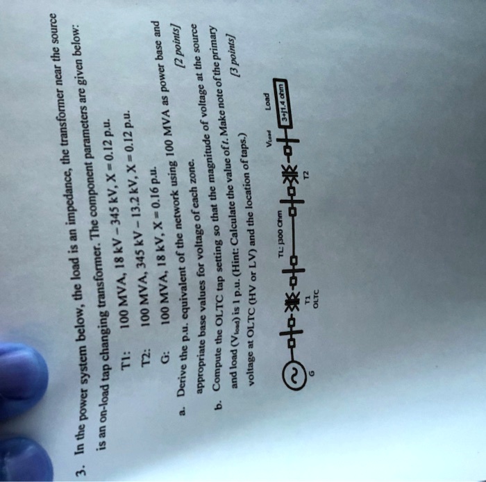
3. In the power system below, the load is an impedance, the transformer near the source
is an on-load tap changing transformer. The component parameters are given below:
100 MVA, 18 kV - 345 kV, X = 0.12 p.u.
T1:
100 MVA, 345 kV - 13.2 kV, X = 0.12 p.u.
T2:
G:
100 MVA, 18 kV, X = 0.16 p.u.
a. Derive the p.u. equivalent of the network using 100 MVA as power base and
appropriate base values for voltage of each zone.
[2 points]
b. Compute the OLTC tap setting so that the magnitude of voltage at the source
and load ($V_{load}$) is 1 p.u. (Hint: Calculate the value of 1. Make note of the primary
voltage at OLTC (HV or LV) and the location of taps.)
[3 points]
TL: j300 Ohm
\(\sim\) \(\bigstar\) \(\bigstar\) \(\bigstar\) \(\bigstar\) \(\bigstar\)
G
T1
OLTC
T2
$V_{load}$
Load
3+j1.4 ohm