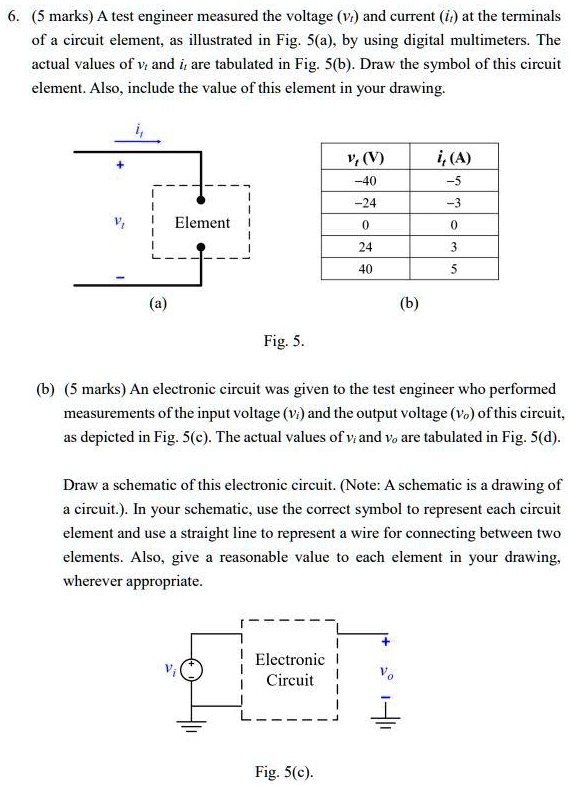
6. (5 marks) A test engineer measured the voltage ($v_i$) and current ($i_i$) at the terminals
of a circuit element, as illustrated in Fig. 5(a), by using digital multimeters. The
actual values of $v_i$ and $i_i$ are tabulated in Fig. 5(b). Draw the symbol of this circuit
element. Also, include the value of this element in your drawing.
$i_i$
$v_i$ (V) $i_i$ (A)
-40 -5
-24 -3
0 0
24 3
40 5
(a) (b)
Fig. 5.
(b) (5 marks) An electronic circuit was given to the test engineer who performed
measurements of the input voltage ($v_i$) and the output voltage ($v_o$) of this circuit,
as depicted in Fig. 5(c). The actual values of $v_i$ and $v_o$ are tabulated in Fig. 5(d).
Draw a schematic of this electronic circuit. (Note: A schematic is a drawing of
a circuit.). In your schematic, use the correct symbol to represent each circuit
element and use a straight line to represent a wire for connecting between two
elements. Also, give a reasonable value to each element in your drawing,
wherever appropriate.
+
$v_i$
Electronic
Circuit
$v_o$
Fig. 5(c).