Question 1
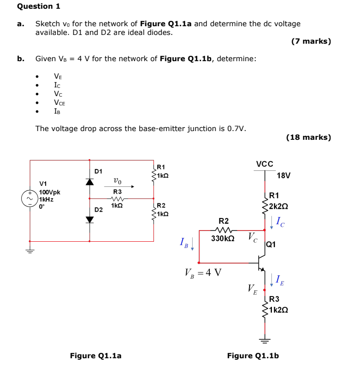
a. Sketch v0 for the network of Figure Q1.1a and determine the dc voltage available. D1 and D2 are ideal diodes.
b. Given VB = 4 V for the network of Figure Q1.1b, determine:
• VE
• IC
• VC
• VCE
• IB
The voltage drop across the base-emitter junction is 0.7V.
Figure Q1.1a
Figure Q1.1b