I need help with number 2.
This exercise is intended to analyze the functional block diagram of the data-path given in Fig. 4.17 (slide 28). For each of the following instructions:
1. add $t0, $s1, $t1
2. lw $t1, 400($s0)
3. beq $t2, $zero, doit
a. List and describe the function of each block in the data-path involved in the execution of each of the instructions in the list.
b. Identify the control lines and assert or de-assert them accordingly as needed for the successful execution of each instruction.
c. Also, for each instruction determine the binary values of the ALUOp lines and the output F that selects the operation of the ALU.
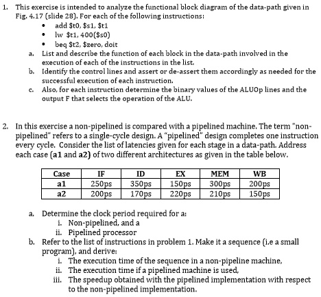
2. In this exercise, a non-pipelined machine is compared with a pipelined machine. The term "non-pipelined" refers to a single-cycle design. A "pipelined" design completes one instruction every cycle. Consider the list of latencies given for each stage in a data-path. Address each case (a1 and a2) of two different architectures as given in the table below.
Case a1 a2
IF 250ps 200ps
ID 350ps 170ps
EX 150ps 220ps
MEM 300ps 210ps
WB 200ps 150ps
a. Determine the clock period required for:
i. Non-pipelined processor
ii. Pipelined processor
b. Refer to the list of instructions in problem 1. Make it a sequence (i.e., a small program), and derive:
i. The execution time of the sequence in a non-pipelined machine
ii. The execution time if a pipelined machine is used
iii. The speedup obtained with the pipelined implementation with respect to the non-pipelined implementation.