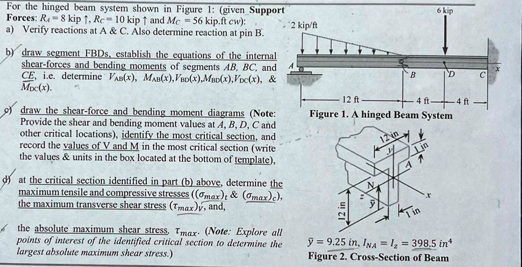
For the hinged beam system shown in Figure 1: (given Support Forces: $R_A = 8$ kip $\uparrow$, $R_C = 10$ kip $\uparrow$ and $M_C = 56$ kip.ft cw):
a) Verify reactions at A & C. Also determine reaction at pin B.
b) draw segment FBDs, establish the equations of the internal shear-forces and bending moments of segments AB, BC, and CE, i.e. determine $V_{AB}(x)$, $M_{AB}(x)$, $V_{BD}(x)$, $M_{BD}(x)$, $V_{DC}(x)$, & $M_{DC}(x)$.
c) draw the shear-force and bending moment diagrams (Note: Provide the shear and bending moment values at A, B, D, C and other critical locations), identify the most critical section, and record the values of V and M in the most critical section (write the values & units in the box located at the bottom of template),
d) at the critical section identified in part (b) above, determine the maximum tensile and compressive stresses (($\sigma_{max}$)$_t$ & ($\sigma_{max}$)$_c$), the maximum transverse shear stress ($\tau_{max}$)$_v$, and,
e) the absolute maximum shear stress, $\tau_{max}$. (Note: Explore all points of interest of the identified critical section to determine the largest absolute maximum shear stress.)
Figure 1. A hinged Beam System
Figure 2. Cross-Section of Beam
2 kip/ft
6 kip
12 ft
4 ft
4 ft
12 in
1 in
1 in
12 in
$\bar{y} = 9.25$ in, $I_{NA} = I_z = 398.5$ in$^4$