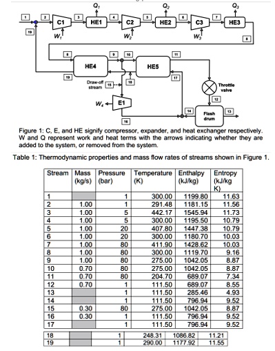
Figure 1 shows a block diagram for the Claude process that is used to liquefy methane. The Claude process serves as an example to comprehensively synthesize all the concepts taught from week 1 to week 6 of CH2123. Fresh methane (stream 1) is combined with recycled methane (stream 19) and then compressed, and C3 to 80 bar. Intercoolers (HE1, HE2, and HE3) after each compressor remove heat from the incoming gas. The compressed methane is then further cooled in heat exchangers HE4 and HE5 before being throttled. The flash drum operates at 1 bar. Liquid methane exits the flash drum in stream 13 (saturated liquid, 1 bar). A draw-off stream (stream 15, 0.30 k(g)/(s)) is passed through an expander (E1) before combining with the un-liquefied methane stream (stream 14, saturated vapor at 1 bar) and is then recycled back (streams 17, 18, and 19). The draw-off stream leaves the expander as a saturated vapor at 1 bar. Table 1 contains the temperature, pressure, specific enthalpy, and specific entropy of all streams. Selected mass flow rates are also provided. All compressors and expanders are adiabatic. Assume all processes to be at steady state. Neglect the kinetic and potential energy terms. a. Determine whether the compressors C1, C2, and C3 and the expander E1, are reversible or irreversible. Figure 1: C, E, and HE signify compressor, expander, and heat exchanger respectively. W and Q represent work and heat terms with the arrows indicating whether they are added to the system, or removed from the system. Table 1: Thermodynamic properties and mass flow rates of streams shown in Figure 1. b. Calculate the work inputs to compressors C1, C2, and C3, and the work obtained from expander E1 in units of k(J)/(s). c. Determine the efficiency of the expander E1. The exhaust from the expander is saturated vapor at 1 bar (stream 16). d. Calculate the mass flow rate (k(g)/(s)) of liquefied methane exiting the system (stream 13). HE1 4 C2 im C1 I'M HE2 C3 w! HE3 HE4 HE5 W E1 Figure 1: C, E, and HE signify compressor, expander, and heat exchanger respectively. W and Q represent work and heat terms with the arrows indicating whether they are added to the system, or removed from the system. Table 1: Thermodynamic properties and mass flow rates of streams shown in Figure 1. Stream Mass Pressure Temperature Enthalpy Entropy (kg/s) (bar) (K) (kJ/kg) (kJ/kg K) 1 1 300.00 1199.80 11.63 2 1.00 291.48 1181.15 11.56 3 1.00 5 442.17 1545.94 11.73 4 1.00 5 300.00 1195.50 10.79 5 1.00 20 407.80 1447.38 10.79 6 1.00 20 300.00 1180.70 10.03 7 1.00 80 411.90 1428.62 10.03 8 1.00 80 300.00 1119.70 9.16 9 1.00 80 275.00 1042.05 8.87 10 0.70 80 275.00 1042.05 8.87 11 0.70 80 204.70 689.07 7.34 12 0.70 1 111.50 689.07 8.55 13 1 111.50 285.46 4.93 14 1 111.50 796.94 9.52 15 0.30 80 275.00 1042.05 8.87 16 0.30 1 111.50 796.94 9.52 17 1 111.50 796.94 9.52 18 1 248.31 1086.82 11.21 19 290.001177.92 11.55