In class, we derived a state machine for a robot vacuum that was implemented using D flip-flops. The example and solution are available here: robot vacuum cleaner example.pdf
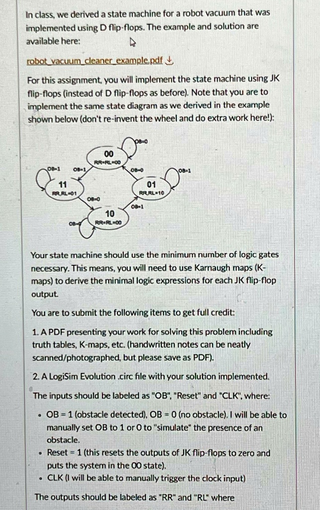
For this assignment, you will implement the state machine using JK flip-flops instead of D flip-flops as before. Note that you are to implement the same state diagram as we derived in the example shown below (don't re-invent the wheel and do extra work here!):
00 RR=RL=00
11 RRRL
01 RRRL
10 RR=RL=00
Your state machine should use the minimum number of logic gates necessary. This means, you will need to use Karnaugh maps (K-maps) to derive the minimal logic expressions for each JK flip-flop output.
You are to submit the following items to get full credit:
1. A PDF presenting your work for solving this problem including truth tables, K-maps, etc. (handwritten notes can be neatly scanned/photographed, but please save as PDF).
2. A LogiSim Evolution .circ file with your solution implemented.
The inputs should be labeled as "OB", "Reset", and "CLK", where:
- OB = 1 (obstacle detected), OB = 0 (no obstacle), I will be able to manually set OB to 1 or 0 to "simulate" the presence of an obstacle.
- Reset = 1 (this resets the outputs of JK flip-flops to zero and puts the system in the 00 state).
- CLK (I will be able to manually trigger the clock input).
The outputs should be labeled as "RR" and "RL".