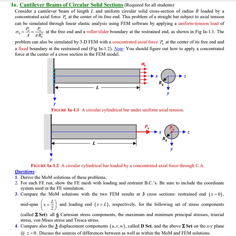
Ia. Cantilever Beams of Circular Solid Sections (Required for all students) Consider a cantilever beam of length L and uniform circular solid cross-section of radius R loaded by a concentrated axial force P at the center of its free end. This problem of a straight bar subject to axial tension can be simulated through linear elastic analysis using FEM software by applying a uniform-tension load of P at the free end and a roller/slider boundary at the restrained end, as shown in Fig Ia-1.1. The ATR problem can also be simulated by 3-D FEM with a concentrated axial force P at the center of its free end and a fixed boundary at the restrained end (Fig Ia-1.2). Note: You should figure out how to apply a concentrated force at the center of a cross section in the FEM model.
FIGURE Ia-1.1 A circular cylindrical bar under uniform axial tension
FIGURE Ia-1.2 A circular cylindrical bar loaded by a concentrated axial force through C.A.
Questions:
1. Derive the MoM solutions of these problems.
2. For each FE run, show the FE mesh with loading and restraint B.C.'s. Be sure to include the coordinate system used in the FE simulation.
3. Compare the MoM solutions with the two FEM results at 3 cross sections: restrained end (x=0), mid-span, and loading end (x=L), respectively, for the following set of stress components called Set: all 6 Cartesian stress components, the maximum and minimum principal stresses, triaxial stress, von Mises stress, and Tresca stress.
4. Compare also the 3 displacement components (u, v, w), called D Set, and the above Set on the x-y plane @ z = 0. Discuss the sources of differences between as well as within the MoM and FEM solutions.