Question 3
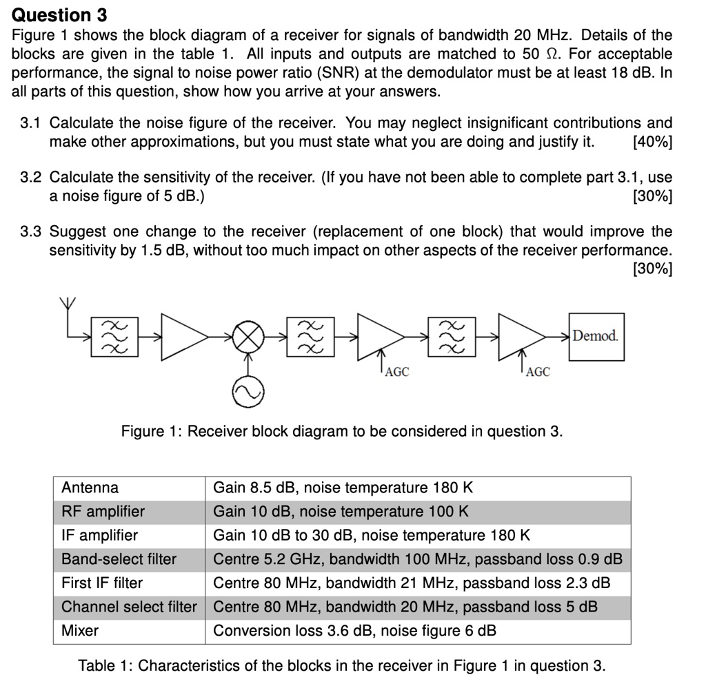
Figure 1 shows the block diagram of a receiver for signals of bandwidth 20 MHz. Details of the blocks are given in the table 1. All inputs and outputs are matched to 50 Ω. For acceptable performance, the signal to noise power ratio (SNR) at the demodulator must be at least 18 dB. In all parts of this question, show how you arrive at your answers.
3.1 Calculate the noise figure of the receiver. You may neglect insignificant contributions and make other approximations, but you must state what you are doing and justify it. [40%]
3.2 Calculate the sensitivity of the receiver. (If you have not been able to complete part 3.1, use a noise figure of 5 dB.) [30%]
3.3 Suggest one change to the receiver (replacement of one block) that would improve the sensitivity by 1.5 dB, without too much impact on other aspects of the receiver performance. [30%]
Antenna Gain 8.5 dB, noise temperature 180 K
RF amplifier Gain 10 dB, noise temperature 100 K
IF amplifier Gain 10 dB to 30 dB, noise temperature 180 K
Band-select filter Centre 5.2 GHz, bandwidth 100 MHz, passband loss 0.9 dB
First IF filter Centre 80 MHz, bandwidth 21 MHz, passband loss 2.3 dB
Channel select filter Centre 80 MHz, bandwidth 20 MHz, passband loss 5 dB
Mixer Conversion loss 3.6 dB, noise figure 6 dB
Table 1: Characteristics of the blocks in the receiver in Figure 1 in question 3.