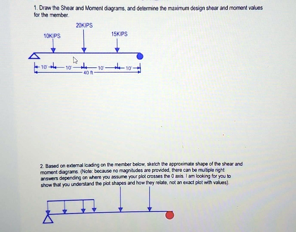
1. Draw the Shear and Moment diagrams, and determine the maximum design shear and moment values for the member.
20KIPS
10KIPS
15KIPS
10' 10' 10' 10'
40 ft
2. Based on external loading on the member below, sketch the approximate shape of the shear and moment diagrams. (Note: because no magnitudes are provided, there can be multiple right answers depending on where you assume your plot crosses the 0 axis. I am looking for you to show that you understand the plot shapes and how they relate, not an exact plot with values).