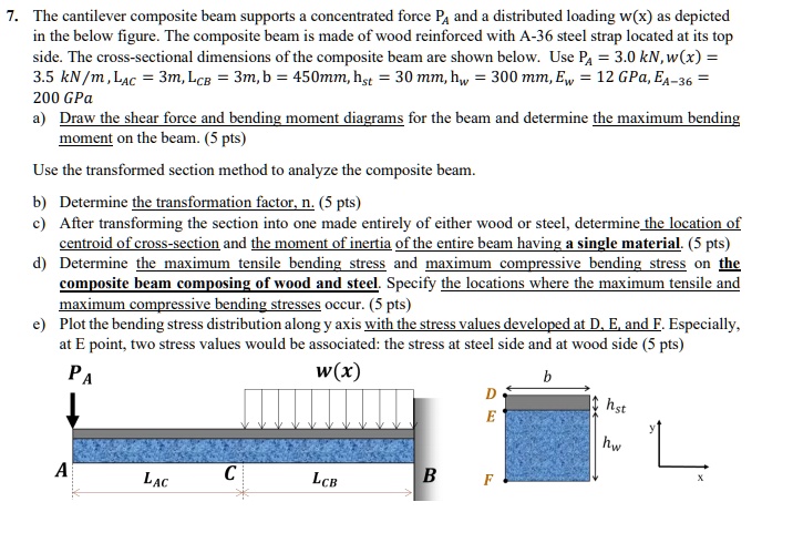
7. The cantilever composite beam supports a concentrated force P and a distributed loading w(x) as depicted in the figure below. The composite beam is made of wood reinforced with A-36 steel strap located at its top side. The cross-sectional dimensions of the composite beam are shown below. Use Pa = 3.0 kN, w(x) = 3.5 kN/m, LAc = 3m, LcB = 3m, b = 450mm, hst = 30mm, hw = 300mm, Ew = 12 GPa, EA-36 = 200 GPa.
a) Draw the shear force and bending moment diagrams for the beam and determine the maximum bending moment on the beam. (5 pts)
Use the transformed section method to analyze the composite beam.
b) Determine the transformation factor, n. (5 pts)
c) After transforming the section into one made entirely of either wood or steel, determine the location of the centroid of the cross-section and the moment of inertia of the entire beam having a single material. (5 pts)
d) Determine the maximum tensile bending stress and maximum compressive bending stress on the composite beam composed of wood and steel. Specify the locations where the maximum tensile and maximum compressive bending stresses occur. (5 pts)
Plot the bending stress distribution along the y-axis with the stress values developed at points D, E, and F. Especially at point E, two stress values would be associated: the stress at the steel side and at the wood side. (5 pts)
PA w(x) b D hst E
A
LAc
LCB
B