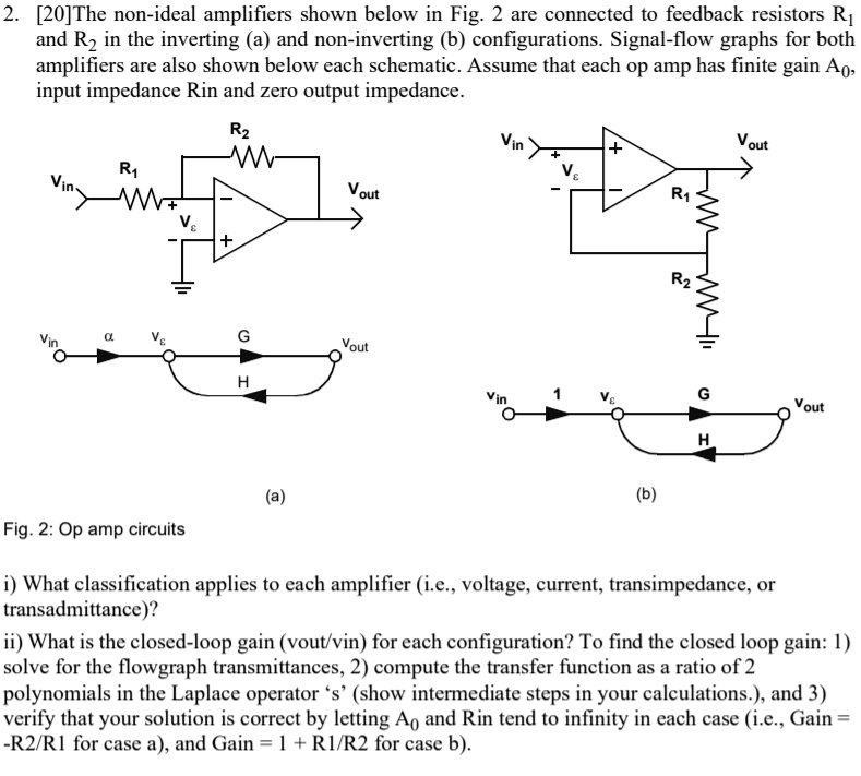
2. [20]The non-ideal amplifiers shown below in Fig. 2 are connected to feedback resistors R?
and R? in the inverting (a) and non-inverting (b) configurations. Signal-flow graphs for both
amplifiers are also shown below each schematic. Assume that each op amp has finite gain A?,
input impedance R?? and zero output impedance.
V??
R?
V??
+
V_
{out}
+
R?
V_
{?}
+
V_
{out}
R?
V_
{?}
+
V??
?
V_
{?}
G
V_
{out}
H
(a)
R?
V??
1
V_
{?}
G
V_
{out}
H
(b)
Fig. 2: Op amp circuits
i) What classification applies to each amplifier (i.e., voltage, current, transimpedance, or
transadmittance)?
ii) What is the closed-loop gain (v_
{out}/v_
{in}) for each configuration? To find the closed loop gain: 1)
solve for the flowgraph transmittances, 2) compute the transfer function as a ratio of 2
polynomials in the Laplace operator 's' (show intermediate steps in your calculations.), and 3)
verify that your solution is correct by letting A? and R?? tend to infinity in each case (i.e., Gain =
-R?/R? for case a), and Gain = 1 + R?/R? for case b).