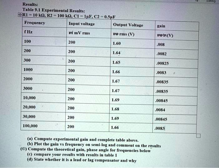
Results:
Table 9.1 Experimental Results:
+R1 = 10 k$\Omega$, R2 = 100 k$\Omega$, C1 = 1$\mu$F, C2 = 0.5$\mu$F
Frequency
Input voltage
Output Voltage
gain
f Hz
vi mV rms
vo rms (V)
$v_o/v_i$(V)
100
200
1.60
.008
200
200
1.64
.0082
300
200
1.65
.00825
1000
200
1.66
.0083
2000
200
1.67
.00835
3000
200
1.67
.00835
10,000
200
1.69
.00845
20,000
200
1.68
.0084
30,000
200
1.69
.00845
100,000
200
1.66
.0083
(a) Compute experimental gain and complete table above.
(b) Plot the gain vs frequency on semi-log and comment on the results
(c) Compute the theoretical gain, phase angle for frequencies below
(c) compare your results with results in table 1
(d) State whether it is a lead or lag compensator and why