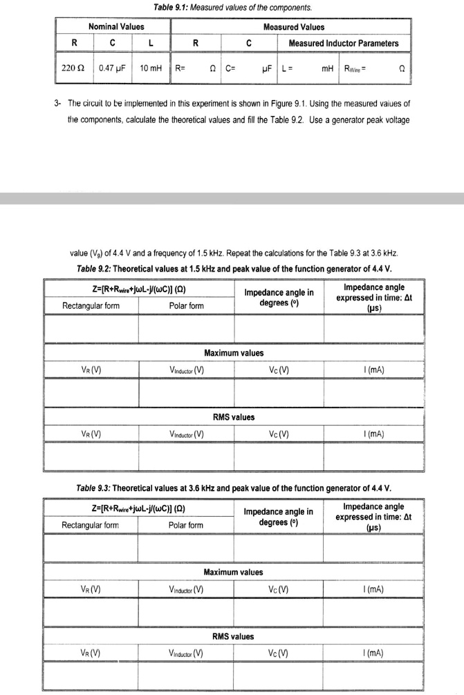
Table 9.1: Measured values of the components.
Nominal Values
Measured Values
R
C
L
R
C
Measured Inductor Parameters
220 ? 0.47 µF
10 mH
R=
? C=
µF L=
mH Rwire=
?
3- The circuit to be implemented in this experiment is shown in Figure 9.1. Using the measured values of
the components, calculate the theoretical values and fill the Table 9.2. Use a generator peak voltage
value (Vg) of 4.4 V and a frequency of 1.5 kHz. Repeat the calculations for the Table 9.3 at 3.6 kHz.
Table 9.2: Theoretical values at 1.5 kHz and peak value of the function generator of 4.4 V.
Z=[R+Rwire+j?L-j/(?C)] (?)
Rectangular form
Polar form
Impedance angle in
degrees (°)
Impedance angle
expressed in time: ?t
(?s)
Maximum values
VR (V)
Vinductor (V)
Vc (V)
I (mA)
RMS values
VR (V)
Vinductor (V)
Vc (V)
I (mA)
Table 9.3: Theoretical values at 3.6 kHz and peak value of the function generator of 4.4 V.
Z=[R+Rwire+j?L-j/(?C)] (?)
Rectangular form
Polar form
Impedance angle in
degrees (°)
Impedance angle
expressed in time: ?t
(?s)
Maximum values
VR (V)
Vinductor (V)
Vc (V)
I (mA)
RMS values
VR (V)
Vinductor (V)
Vc (V)
I (mA)