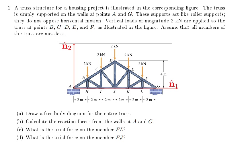
1. A truss structure for a housing project is illustrated in the corresponding figure. The truss
is simply supported on the walls at points A and G. These supports act like roller supports;
they do not oppose horizontal motion. Vertical loads of magnitude 2 kN are applied to the
truss at points B, C, D, E, and F, as illustrated in the figure. Assume that all members of
the truss are massless.
\hat{\mathbf{n}}_2
2 kN
2 kN
2 kN
D
2 kN
2 kN
C
E
4 m
B
F
A
G
\hat{\mathbf{n}}_1
H
I
J
K
L
-2 m -2 m -2 m -2 m -2 m -2 m -
(a) Draw a free body diagram for the entire truss.
(b) Calculate the reaction forces from the walls at A and G.
(c) What is the axial force on the member FL?
(d) What is the axial force on the member EJ?