UT DALLAS
EE3301, Fall 2017
Department of Electrical Engineering,
University of Texas -Dallas
Problem 1 (100 points):
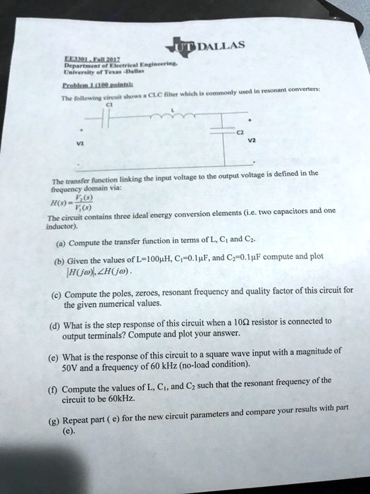
The following circuit shows a CLC filter which is commonly used in resonant converters:
C1
V1
C2
V2
The transfer function linking the input voltage to the output voltage is defined in the
frequency domain via:
$H(s) = \frac{V_2(s)}{V_1(s)}$
The circuit contains three ideal energy conversion elements (i.e. two capacitors and one
inductor).
(a) Compute the transfer function in terms of L, C?, and C?.
(b) Given the values of L=100µH, C?=0.1µF, and C?=0.1 µF compute and plot
$H(j\omega)$, $\angle H(j\omega)$.
(c) Compute the poles, zeroes, resonant frequency and quality factor of this circuit for
the given numerical values.
(d) What is the step response of this circuit when a 10? resistor is connected to
output terminals? Compute and plot your answer.
(e) What is the response of this circuit to a square wave input with a magnitude of
50V and a frequency of 60 kHz (no-load condition).
(f) Compute the values of L, C?, and C? such that the resonant frequency of the
circuit to be 60kHz.
(g) Repeat part (e) for the new circuit parameters and compare your results with part
(e).