$\text{Z}_{eq1} = j1.058 \Omega$
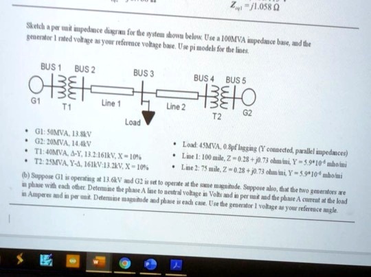
Sketch a per unit impedance diagram for the system shown below. Use a 100MVA impedance base, and the
generator 1 rated voltage as your reference voltage base. Use pi models for the lines.
BUS 1 BUS 2
BUS 3
BUS 4 BUS 5
\text{G1} \quad \begin{smallmatrix} \text{m} \\ \text{m} \\ \text{m} \\ \end{smallmatrix} \quad \text{T1} \quad \text{Line 1} \quad \text{Line 2} \quad \begin{smallmatrix} \text{m} \\ \text{m} \\ \text{m} \\ \end{smallmatrix} \quad \text{T2} \quad \text{G2}
Load
$\bullet$ G1: 50MVA, 13.8kV
$\bullet$ G2: 20MVA, 14.4kV
$\bullet$ T1: 40MVA, $\Delta$-Y, 13.2:161kV, X = 10%
$\bullet$ T2: 25MVA, Y-$\Delta$, 161kV:13.2kV, X = 10%
$\bullet$ Load: 45MVA, 0.8pf lagging (Y connected, parallel impedances)
$\bullet$ Line 1: 100 mile, Z = 0.28 + j0.73 ohm/mi, Y = $5.9 \times 10^{-6}$ mho/mi
$\bullet$ Line 2: 75 mile, Z = 0.28 + j0.73 ohm/mi, Y = $5.9 \times 10^{-6}$ mho/mi
(b) Suppose G1 is operating at 13.6kV and G2 is set to operate at the same magnitude. Suppose also, that the two generators are
in phase with each other. Determine the phase A line to neutral voltage in Volts and in per unit and the phase A current at the load
in Amperes and in per unit. Determine magnitude and phase is each case. Use the generator 1 voltage as your reference angle.