+
42
a1
+
y(t)
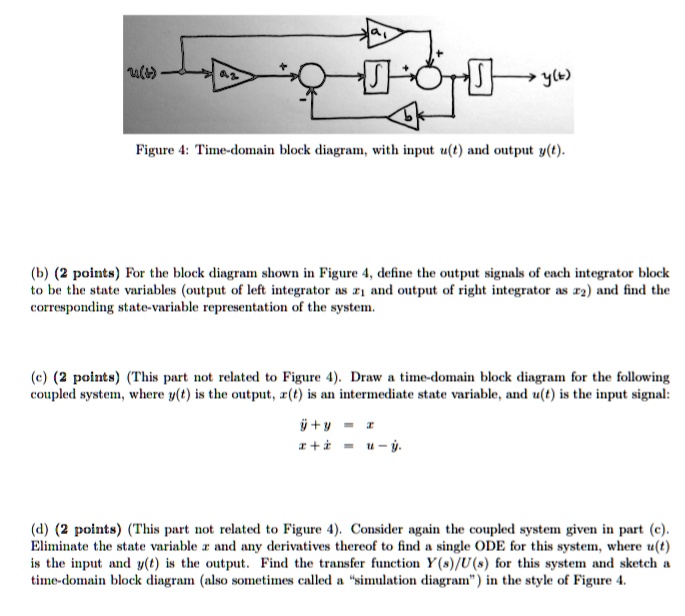
Figure 4: Time-domain block diagram, with input u(t) and output y(t).
(b) (2 points) For the block diagram shown in Figure 4, define the output signals of each integrator block
to be the state variables (output of left integrator as $x_1$ and output of right integrator as $x_2$) and find the
corresponding state-variable representation of the system.
(c) (2 points) (This part not related to Figure 4). Draw a time-domain block diagram for the following
coupled system, where $y(t)$ is the output, $x(t)$ is an intermediate state variable, and $u(t)$ is the input signal:
$\dot{y} + y = x$
$\dot{x} + \dot{x} = u - y$.
(d) (2 points) (This part not related to Figure 4). Consider again the coupled system given in part (c).
Eliminate the state variable $x$ and any derivatives thereof to find a single ODE for this system, where $u(t)$
is the input and $y(t)$ is the output. Find the transfer function $Y(s)/U(s)$ for this system and sketch a
time-domain block diagram (also sometimes called a \"simulation diagram\") in the style of Figure 4.