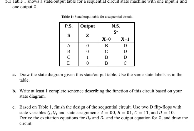
5.1 Table I shows a state/output table for a sequential circuit state machine with one input X and one output Z.
Table 1: State/output table for a sequential circuit.
P.S.
Output
N.S.
S+
S
Z
X=0
X=1
A
0
B
D
B
0
C
D
C
1
B
D
D
0
B
C
a. Draw the state diagram given this state/output table. Use the same state labels as in the table.
b. Write at least 1 complete sentence describing the function of this circuit based on your state diagram.
c. Based on Table 1, finish the design of the sequential circuit. Use two D flip-flops with state variables $Q_2Q_1$ and state assignments A = 00, B = 01, C = 11, and D = 10. Derive the excitation equations for $D_2$ and $D_1$ and the output equation for Z, and draw the circuit.