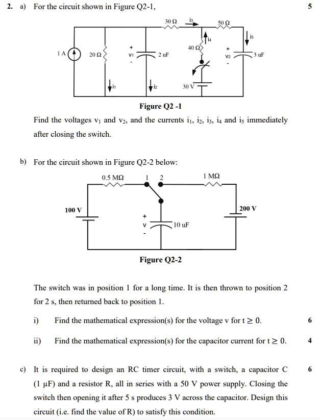
2. a) For the circuit shown in Figure Q2-1,
30 ?
i?
50 ?
i?
1?
40 ?
1 A
20 ?
2 µF
v?
v?
3 µF
i?
i?
30 V
Figure Q2 -1
Find the voltages $v_1$ and $v_2$, and the currents $i_1$, $i_2$, $i_3$, $i_4$ and $i_5$ immediately
after closing the switch.
b) For the circuit shown in Figure Q2-2 below:
100 V
0.5 M?
1
2
1 M?
200 V
10 µF
Figure Q2-2
The switch was in position 1 for a long time. It is then thrown to position 2
for 2 s, then returned back to position 1.
i) Find the mathematical expression(s) for the voltage v for $t \ge 0$.
ii) Find the mathematical expression(s) for the capacitor current for $t \ge 0$.
c) It is required to design an RC timer circuit, with a switch, a capacitor C
(1 µF) and a resistor R, all in series with a 50 V power supply. Closing the
switch then opening it after 5 s produces 3 V across the capacitor. Design this
circuit (i.e. find the value of R) to satisfy this condition.