Learning Goal:
To calculate the component values for high-Q bandpass and bandreject filters to meet frequency domain specifications.
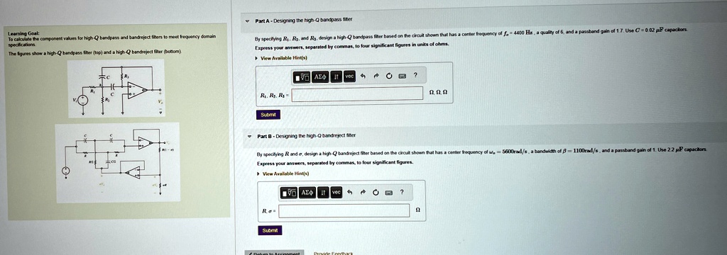
The figures show a high-Q bandpass filter (top) and a high-Q bandreject filter (bottom).
Part A - Designing the high-Q bandpass filter
By specifying $R_1$, $R_2$, and $R_3$, design a high-Q bandpass filter based on the circuit shown that has a center frequency of $f_c = 4400 Hz$, a quality of 6, and a passband gain of 1.7. Use $C = 0.02 \mu F$ capacitors.
Express your answers, separated by commas, to four significant figures in units of ohms.
Part B - Designing the high-Q bandreject filter
By specifying $R$ and $\alpha$, design a high-Q bandreject filter based on the circuit shown that has a center frequency of $\omega_c = 5600 rad/s$, a bandwidth of $\beta = 1100 rad/s$, and a passband gain of 1. Use $2.2 \mu F$ capacitors.
Express your answers, separated by commas, to four significant figures.