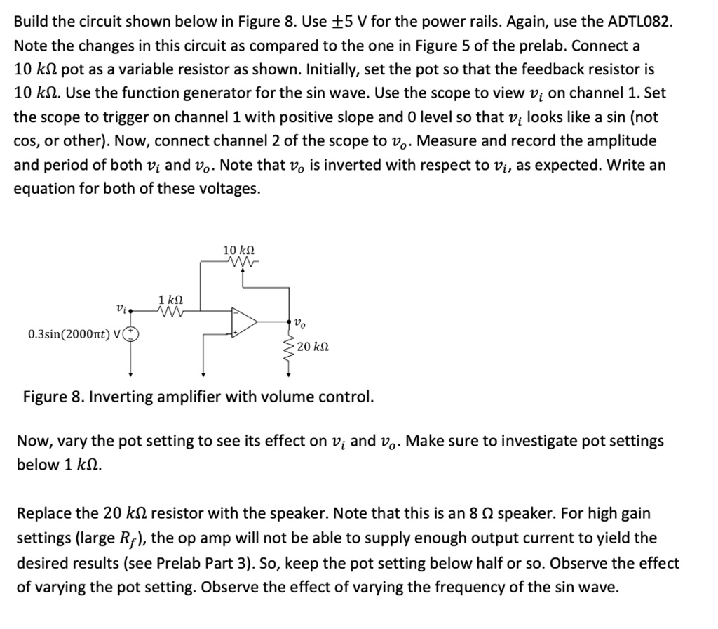
Build the circuit shown below in Figure 8. Use \(\pm 5\) V for the power rails. Again, use the ADTL082.
Note the changes in this circuit as compared to the one in Figure 5 of the prelab. Connect a
10 k\(\Omega\) pot as a variable resistor as shown. Initially, set the pot so that the feedback resistor is
10 k\(\Omega\). Use the function generator for the sin wave. Use the scope to view \(v_i\) on channel 1. Set
the scope to trigger on channel 1 with positive slope and 0 level so that \(v_i\) looks like a sin (not
cos, or other). Now, connect channel 2 of the scope to \(v_o\). Measure and record the amplitude
and period of both \(v_i\) and \(v_o\). Note that \(v_o\) is inverted with respect to \(v_i\), as expected. Write an
equation for both of these voltages.
\(v_i\)
1 k\(\Omega\)
0.3sin\((2000\pi t)\) V
10 k\(\Omega\)
\(v_o\)
20 k\(\Omega\)
Figure 8. Inverting amplifier with volume control.
Now, vary the pot setting to see its effect on \(v_i\) and \(v_o\). Make sure to investigate pot settings
below 1 k\(\Omega\).
Replace the 20 k\(\Omega\) resistor with the speaker. Note that this is an 8 \(\Omega\) speaker. For high gain
settings (large \(R_f\)), the op amp will not be able to supply enough output current to yield the
desired results (see Prelab Part 3). So, keep the pot setting below half or so. Observe the effect
of varying the pot setting. Observe the effect of varying the frequency of the sin wave.