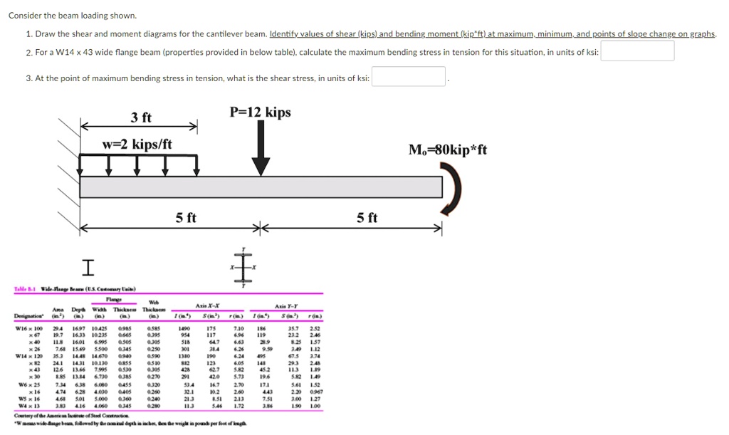
Consider the beam loading shown.
1. Draw the shear and moment diagrams for the cantilever beam. Identify values of shear (kips) and bending moment (kip*ft) at maximum, minimum, and points of slope change on graphs.
2. For a W14 x 43 wide flange beam (properties provided in the table below), calculate the maximum bending stress in tension for this situation, in units of ksi:
3. At the point of maximum bending stress in tension, what is the shear stress, in units of ksi:
P = 12 kips
3 ft
w = 2 kips/ft
Mo = 80 kip*ft
5 ft
5 ft
Table:
Flange Web Axis X-X Width Thickness Axis YY Depth Thickness (in^2) (in.) (in) (in.) (in) (in.) S (in^3) r (in) S (in^3) r (in)
W16 x 100 29.4 16.97 10.425 0.985 6.7 19.7 16.33 10.235 0.665 1.7 7.49 11.8 16.01 6.995 0.505 9.395 6.63 1.57 x 26 7.68 15.69 5.500 0.345 0.250 6.26 1.12
W14 x 120 35.3 14.48 14.670 0.940 9.590 1380 190 6.24 67.5 3.74 24.1 14.31 10.130 0.855 0.510 12.6 13.66 7.995 0.530 0.395 12.2 39 8.85 13.84 6.730 0.385 9.270 291 42.9 5.73 19.6 5.82 1.49
W6 x 25 7.34 6.38 6.080 0.455 9.330 53.4 16.7 17.1 5.61 1.52 16 4.74 6.28 4.030 0.405 9.269 32.1 19.2 0.967
W5 x 16 4.68 5.01 5.000 0.360 9.240 13 2.13 3.83 4.16 0.345 0.290 127
W4 x 13 4.060 1.72