Experiment 2: BJT as a switch
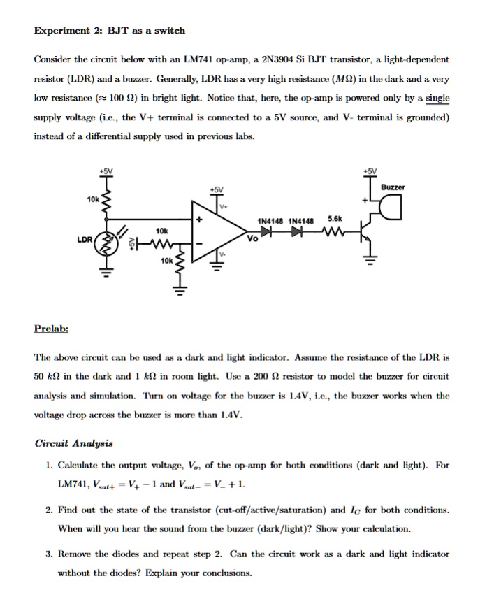
Consider the circuit below with an LM741 op-amp, a 2N3904 Si BJT transistor, a light-dependent
resistor (LDR) and a buzzer. Generally, LDR has a very high resistance (ΜΩ) in the dark and a very
low resistance (≈ 100 2) in bright light. Notice that, here, the op-amp is powered only by a single
supply voltage (i.e., the V+ terminal is connected to a 5V source, and V- terminal is grounded)
instead of a differential supply used in previous labs.
+5V
+5V
10k
V
+
10k
LDR
1N4148 1N4148 5.6k
Vo
V-
10k
+5V
Buzzer
Prelab:
The above circuit can be used as a dark and light indicator. Assume the resistance of the LDR is
50 kn in the dark and 1 ko in room light. Use a 2002 resistor to model the buzzer for circuit
analysis and simulation. Turn on voltage for the buzzer is 1.4V, i.e., the buzzer works when the
voltage drop across the buzzer is more than 1.4V.
Circuit Analysis
1. Calculate the output voltage, Vo, of the op-amp for both conditions (dark and light). For
LM741, Vsat+V+1 and Vsat- = V_ +1.
2. Find out the state of the transistor (cut-off/active/saturation) and Ic for both conditions.
When will you hear the sound from the buzzer (dark/light)? Show your calculation.
3. Remove the diodes and repeat step 2. Can the circuit work as a dark and light indicator
without the diodes? Explain your conclusions.