1. A single-phase 50 kVA, 2400/240 volt, 60 Hz distribution transformer is used as a step-down transformer at the load end of a 2400 volt feeder whose series impedance is 1+j2 ohms. The equivalent series impedance of the transformer is (1+j2.5 ohms) referred to the high-voltage (primary) side. The transformer is delivering rated load at 0.8 power factor lagging and at rated secondary voltage. Neglecting the transformer exciting current, determine a) the voltage at the transformer primary terminals, b) the voltage at the sending end of the feeder, and c) the real and reactive power delivered to the sending end of the feeder.
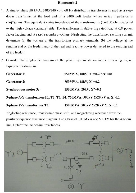
2. Consider the single-line diagram of the power system shown in the following figure. Equipment ratings are:
- Generator 1: 750 MVA, 18 kV, X=0.2 per unit
- Generator 2: 750 MVA, 18 kV, X=0.2 per unit
- Synchronous motor 3: 1500 MVA, 20 kV, X=0.2 per unit
- 3-phase X-Y transformers T1, T2, T3, T4: 750 MVA, 500 kV Y/20 kV X, X=0.1 per unit
- 3-phase Y-Y transformer T5: 1500 MVA, 500 kV Y/20 kV Y, X=0.1 per unit
Neglecting resistance, transformer phase shift, and magnetizing reactance, draw the positive-sequence reactance diagram. Use a base of 100 MVA and 500 kV for the 40-ohm line. Determine the per-unit reactances.
3. Title_with_topic:
- 1. Analysis of a Single-Phase Distribution Transformer in a Power System
- 2. Power System Analysis: Reactance Diagram and Per-Unit Reactances