19ECE201 Analog Electronic Circuits
Homework Sheet 04
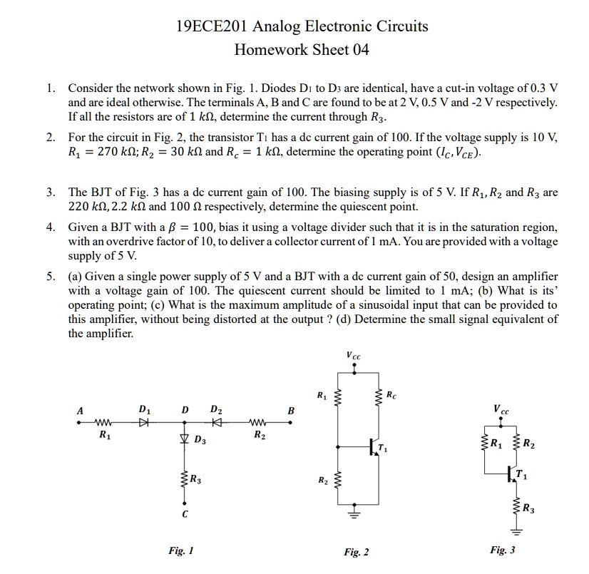
1. Consider the network shown in Fig. 1. Diodes D: to D3 are identical, have a cut-in voltage of 0.3 V and are ideal otherwise. The terminals A, B and C are found to be at 2 V, 0.5 V and -2 V respectively If all the resistors are of 1 k, determine the current through R3. 2. For the circuit in Fig. 2, the transistor Ti has a dc current gain of 100. If the voltage supply is 10 V, R, = 270 k; R = 30 k and Rc = 1 k, determine the operating point (Ic,VcE)
3. The BJT of Fig. 3 has a dc current gain of 100. The biasing supply is of 5 V. If R,R and R3 are 220 k, 2.2 k and 100 respectively, determine the quiescent point. 4. Given a BJT with a = 100, bias it using a voltage divider such that it is in the saturation region with an overdrive factor of 10, to deliver a collector current of 1 mA. You are provided with a voltage supply of 5 V.
5. (a) Given a single power supply of 5 V and a BJT with a dc current gain of 50, design an amplifier with a voltage gain of 100. The quiescent current should be limited to 1 mA; (b) What is its operating point; (c) What is the maximum amplitude of a sinusoidal input that can be provided to this amplifier, without being distorted at the output ? (d) Determine the small signal equivalent of the amplifier.
Vce
R1
A W R1
D1 4I
D
D2 K
B
W R2
R
c
Fig.1
Fig. 2
Fig. 3