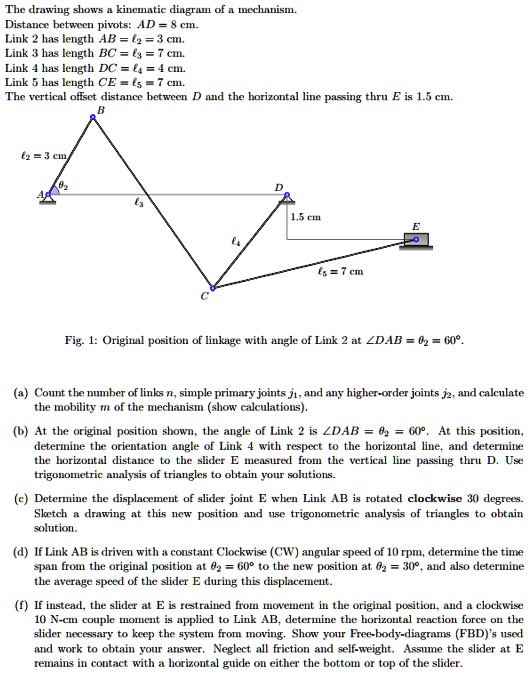
I am having issues with the following problem. Please show me how to do as much of it as you can.
The drawing shows a kinematic diagram of a mechanism. The distance between pivots is AD = 8 cm. Link 2 has a length AB = f2 = 3 cm. Link 3 has a length BC = f3 = 7 cm. Link 4 has a length DC = f4 = 4 cm. Link 5 has a length CE = f5 = 7 cm. The vertical offset distance between D and the horizontal line passing through E is 1.5 cm.
1.5 cm = 7 cm
Fig. 1: Original position of linkage with an angle of Link 2 at DAB = 60°
(a) Count the number of links n, simple primary joints ji, and any higher-order joints j2, and calculate the mobility m of the mechanism (show calculations).
(b) At the original position shown, the angle of Link 2 is DAB = 60°. At this position, determine the orientation angle of Link 4 with respect to the horizontal line, and determine the horizontal distance to the slider E measured from the vertical line passing through D. Use trigonometric analysis of triangles to obtain your solutions.
(c) Determine the displacement of slider joint E when Link AB is rotated clockwise 30 degrees. Sketch a drawing at this new position and use trigonometric analysis of triangles to obtain the solution.
(d) If Link AB is driven with a constant clockwise (CW) angular speed of 10 rpm, determine the time span from the original position at θ2 = 60° to the new position at θ2 = 30°, and also determine the average speed of the slider E during this displacement.
(f) If instead, the slider at E is restrained from movement in the original position, and a clockwise 10 N-cm couple moment is applied to Link AB, determine the horizontal reaction force on the slider necessary to keep the system from moving. Show your Free-body-diagrams (FBD) used and work to obtain your answer. Neglect all friction and self-weight. Assume the slider at E remains in contact with a horizontal guide on either the bottom or top of the slider.