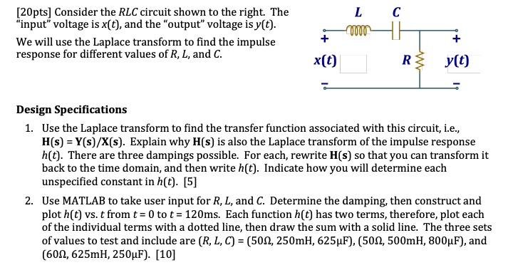
[20pts] Consider the RLC circuit shown to the right. The "input" voltage is x(t), and the "output" voltage is y(t).
We will use the Laplace transform to find the impulse response for different values of R, L, and C.
Design Specifications
1. Use the Laplace transform to find the transfer function associated with this circuit, i.e., H(s) = Y(s)/X(s). Explain why H(s) is also the Laplace transform of the impulse response h(t). There are three dampings possible. For each, rewrite H(s) so that you can transform it back to the time domain, and then write h(t). Indicate how you will determine each unspecified constant in h(t). [5]
2. Use MATLAB to take user input for R, L, and C. Determine the damping, then construct and plot h(t) vs. t from t = 0 to t = 120ms. Each function h(t) has two terms, therefore, plot each of the individual terms with a dotted line, then draw the sum with a solid line. The three sets of values to test and include are (R, L, C) = (50?, 250mH, 625?F), (50?, 500mH, 800?F), and (60?, 625mH, 250?F). [10]