3b. The rod ABC of Figure 3 is made of an aluminum for which E=60 GPa. Knowing that P=10 kN and Q=50 kN, determine the deflection of a point A and point B.
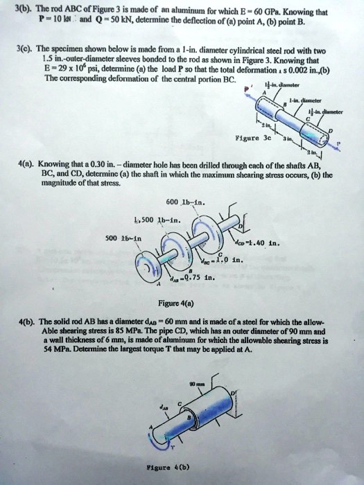
3c. The specimen shown below is made from a 1-in. diameter cylindrical steel rod with two 1.5 in.-outer-diameter sleeves bonded to the rod as shown in Figure 3. Knowing that E=29 x 10^6 psi, determine the load P so that the total deformation is 0.002 in. Also, determine the corresponding deformation of the central portion BC.
Figure 3c
4a. Knowing that a 0.30 in.-diameter hole has been drilled through each of the shafts AB, BC, and CD, determine the shaft in which the maximum shearing stress occurs and the magnitude of that stress.
600 lb-in.
1,500 lb-in.
500 lb-in.
0.40 in
0.75 in
Figure 4a
4b. The solid rod AB has a diameter d=60 mm and is made of a steel for which the allowable shearing stress is 85 MPa. The pipe CD, which has an outer diameter of 90 mm and a wall thickness of 6 mm, is made of aluminum for which the allowable shearing stress is 54 MPa. Determine the largest torque T that may be applied at A.
Figure 4b