(a) Build the circuit shown in Figure 2. It consists of an AC voltage source in series with two 1
?? resistors. Note that the AC source is, of course, a sinusoid supplied by the function
generator. The required Vpk-pk and frequency are labeled as well. You will be using the
oscilloscope to take signal measurements from Vin and Vout in the diagram. Therefore, you
will now require two oscilloscope probes, and you will be using both channels from the
oscilloscope (Channel 1 and Channel 2). ). Channel 1's probe should read the input signal Vin
(the signal coming from the function generator), while Channel 2's probe should measure the
output signal Vout.
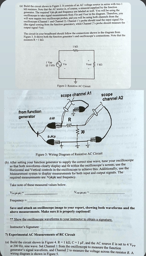
The circuit in your breadboard should follow the connections shown in the diagram from
Figure 3. It shows both the function generator's and oscilloscope's connections. Note that the
resistors R1 ??.
1 ??
1 Vpp
@ 1 kHz
Vin
Vout < 1 ??
Figure 2: Resistive AC Circuit
scope channel A1
scope
channel A2
JA ()
1992
from function
generator
RED
R
(d)
dsarla
BLACK
Figure 3: Wiring Diagram of Resistive AC Circuit
(b) After setting your function generator to supply the correct sine wave, tune your oscilloscope
so that both waveforms clearly display and fit within the oscilloscope's screen; use the
Horizontal and Vertical controls in the oscilloscope to achieve this. Additionally, use the
Measurement system to display measurements for both input and output signals. The
required measurements are: Vpkpk and frequency.
Take note of these measured values below.
Vin (pk-pk) =
Frequency =
Vout (pk-pk) =
Save and attach an oscilloscope image to your report, showing both waveforms and the
above measurements. Make sure it is properly captioned!
** Show the oscilloscope waveforms to your instructor to obtain a signature.
Instructor's Signature:
7) Experimental AC Measurements of RC Circuit
(a) Build the circuit shown in Figure 4. R = 1 ??, C = 1 µF, and the AC source E is set to 4 Vp-p
at 200 Hz, sine wave. Set Channel 1 from the oscilloscope to measure the function
generator's signal waveform, and Channel 2 to measure the voltage across the resistor R. A
wiring diagram is shown in Figure 5.