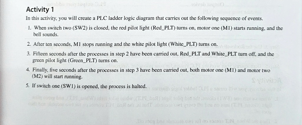
Activity 1
In this activity, you will create a PLC ladder logic diagram that carries out the following sequence of events.
1. When switch two (SW2) is closed, the red pilot light (Red_PLT) turns on, motor one (M1) starts running, and the
bell sounds.
2. After ten seconds, M1 stops running and the white pilot light (White_PLT) turns on.
3. Fifteen seconds after the processes in step 2 have been carried out, Red_PLT and White_PLT turn off, and the
green pilot light (Green_PLT) turns on.
4. Finally, five seconds after the processes in step 3 have been carried out, both motor one (M1) and motor two
(M2) will start running.
5. If switch one (SW1) is opened, the process is halted.