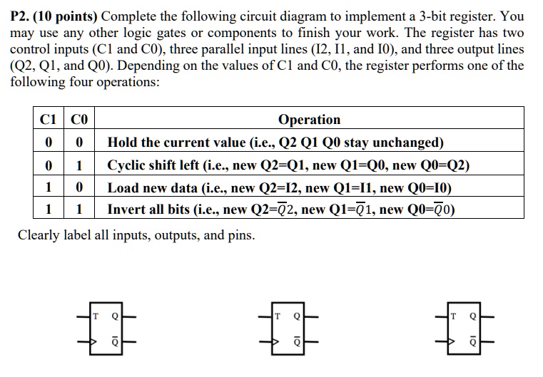
P2. (10 points) Complete the following circuit diagram to implement a 3-bit register. You may use any other logic gates or components to finish your work. The register has two control inputs (C1 and C0), three parallel input lines (I2, I1, and I0), and three output lines (Q2, Q1, and Q0). Depending on the values of C1 and C0, the register performs one of the following four operations:
C1 CO Operation
0 0 Hold the current value (i.e., Q2 Q1 Q0 stay unchanged)
0 1 Cyclic shift left (i.e., new Q2=Q1, new Q1=Q0, new Q0=Q2)
1 0 Load new data (i.e., new Q2=I2, new Q1=I1, new Q0=I0)
1 1 Invert all bits (i.e., new Q2=$\overline{Q2}$, new Q1=$\overline{Q1}$, new Q0=$\overline{Q0}$)
Clearly label all inputs, outputs, and pins.